Study on stress field distribution of hydraulic fracturing

  • Jin-zhou Zhao , 1 ,
  • Jin Zhao 1 ,
  • Yong-quan Hu 1 ,
  • Ting Huang 2 ,
  • Xin-jia Liu 3
Expand
  • 1. State Key Laboratory of Oil & Gas Reservoir Geology and Exploitation, Southwest Petroleum University, Chengdu 610500, China
  • 2. Oil & Gas Technology Research Institute of Changqing Oilfield Company, Xi'an 710018, China
  • 3. China University of Petroleum (Beijing), Beijing 102249, China

Received date: 2019-06-10

  Revised date: 2019-07-10

  Online published: 2020-03-25

Highlights

The stress field has a great influence on fracture turning and expansion and the study on stress distribution has a guiding significance for the fracturing parameters optimization. Based on the extend finite element method, the Abaqus software was used to investigate the influence of principal stress differences and fracture inclines on normal stress and shear stress of fracture, the influence of perforation angles on fracture trajectory, shear stress and tangential displacement, and the influence of fracture spacing on fracture morphology, shear stress and pore pressure. The results show that the normal stress on the fracture decreases with the increase of fracture inclination angle, and the shear stress increases first and then decreases with the increase of fracture inclination angle, reaching the maximum in the direction of 45°. When the fracture angle keeps constant, the normal stress and shear stress on the fracture increase with the increasing perforation angle, and the radius of fracture turning decreases with the increasing perforation angle. With the condition of high principal stress difference and perforation angle of 45°, it is conducive to produce shear failure in the rock of the fracture entrance. In the simultaneous propagation of multiple fractures process, the shear stress in the disturbance region increase with the decrease of fracture spacing and the fluid distribution in the fracture at the disturbance side increase with the increasing fracture spacing. With the condition of great principal stress difference, the perforation method with small cluster spacing and 45° direction is beneficial to shear failure of rocks.

Cite this article

Jin-zhou Zhao , Jin Zhao , Yong-quan Hu , Ting Huang , Xin-jia Liu . Study on stress field distribution of hydraulic fracturing[J]. Natural Gas Geoscience, 2019 , 30(12) : 1677 -1683 . DOI: 10.11764/j.issn.1672-1926.2019.07.012

0 引言

由于致密油、页岩气、煤层气等储层存在基质渗透率低的问题,通常需要借助水平井体积压裂的技术手段进行改造[1,2,3]。随着水平井压裂技术在致密油、页岩气、煤层气领域的广泛应用[4,5,6],水平井裂缝扩展理论也得到逐步发展,国内外形成了大量研究成果[7,8,9,10]。潘林华等[11]利用数值模拟的方法研究了射孔簇数对裂缝干扰的影响,由于模拟过程裂缝延伸轨迹是预先设定的,因此该方法不能研究裂缝扩展的影响因素。曾凡辉等[12]基于致密砂岩天然裂缝与水力裂缝的应力干扰对裂缝间距和射孔参数进行了优化。邓燕等[13]基于均质各向同性二维平面裂缝模型推导了水平井多段压裂应力场模型。赵金洲等[14]基于DDM位移不连续法对裂缝诱导应力进行了研究。李勇明等[15]基于裂缝诱导应力的数学模型,利用DDM方法研究了缝间干扰条件下地应力对裂缝转向角的影响。徐加祥等[16]利用Abaqus软件对缝间干扰和裂缝几何形态进行了研究。以上研究大多未考虑压裂过程中压裂液与岩石变形相互耦合的过程,同时未考虑压裂过程中裂缝壁面正应力和剪应力,以及孔隙压力的变化对裂缝扩展的影响。本文在考虑裂缝扩展流固耦合的条件下,基于扩展有限元方法,利用Abaqus软件研究了裂缝倾角、主应力差对裂缝转向及裂缝壁面应力的影响,以及裂缝间距对剪应力、裂缝几何形态、孔隙压力的影响。

1 数学模型

1.1 岩石应力平衡方程

在水力压裂过程中,假定岩石是一个均质、各向同性的弹性体,岩石变形符合线弹性理论。根据弹性力学原理,平衡方程满足[16]
σ i j , j + f i = 0 ε i j = ( u j , i + u i , j ) / 2 σ i j = C i j k l ε k l
式中:σij 为应力张量;fi 是岩石所受体力;εij 为应变张量;u为介质位移;C为弹性张量。
模型的边界条件为[16]
u = u ¯             Γ u σ n = t ¯         Γ t σ n = p Γ c r
式中: u ¯ t ¯ 分别为边界位移和应变;Γu Γt Γcr 分别为位移、应力和裂缝边界条件;p为裂缝内流体压力,Pa。
在裂缝扩展过程中,由于裂缝尖端应力分布的奇异性,这给裂缝尖端的变形分析造成困难,采用扩展有限元方法能解决这个问题。扩展有限元由标准有限元和裂缝尖端加强单元组成,可以更准确地描述复杂物理场中裂纹的不连续。1999年Belytschko等[17]和Moës等[18]给出位移函数的表达式:
u = I N N I ( x ) u I + I N c r N ̃ I ( x ) ( H ( x ) - H ( x I ) ) a I + I N T I P N ̃ I ( x ) α = 1 4 ( F α ( r , θ ) - F α ( x I ) ) b I α
式中:NI N ̃ I 分别为裂缝尖端一般节点和加强节点位移形函数;uI 为一般节点的位移;H(x)为沿裂纹面的间断跳跃函数;aI 是加强节点有限元位移求解对应的连续部分;Fα (r,θ)为裂缝尖端加强函数;Fα (x)为裂缝尖端应力渐进函数;b I α 为裂缝尖端自由度。
间断跳跃函数定义如下[18]
H ( x ) = 1 ,            x > 0 - 1 ,        x < 0
裂纹尖端加强函数的表达式[18,19]
F α ( r , θ ) α = 1,2 , 3,4 = r s i n θ 2 , r c o s θ 2 , r s i n θ s i n θ 2 , r s i n θ c o s θ 2
r = ( x - x o ) 2 + ( y - y o ) 2 0.5 θ = a r c t a n ( y - y o x - x o )
式中:r为某高斯点在裂尖局部坐标中的极径,m;θ为某高斯点在裂尖局部坐标中的极角,弧度;x为裂缝尖端附近节点横坐标,m;y为裂缝尖端附近节点纵坐标,m;x o为裂缝尖端横坐标,m;y o为裂缝尖端纵坐标,m。

1.2 缝内流动方程

流体在裂缝中流动,满足物质平衡方程,Dahi-Taleghani等[19]给出了方程弱积分形式:
L Δ w Δ t ϕ i ( s ) d s + L q L ( t ) ϕ i ( s ) d s = 1 12 μ 0 L s ( w 3 p s ) ϕ i ( s ) d s
在裂缝入口,外边界条件满足[20]
1 12 μ w 3 p s ϕ i ( s ) 0 = q 0 ϕ 1 ( 0 )
在初始时刻,裂缝端部满足以下条件[20]
1 12 μ w 3 p s ϕ i ( s ) - L , L = 0
式中:w为裂缝宽度,m;t为注入时间,s;φi(s)为节点I的形状函数;q L 为压裂液滤失量,m3μ为流体黏度,Pa·s;s为裂缝长度,m;p为裂缝内压力,Pa;q o为注入排量,m3/min。

1.3 裂缝转向扩展模型

根据线性断裂力学原理可知,裂缝在转向扩展过程中,转向角主要是由Ⅰ型和Ⅱ型裂缝端部应力强度因子决定的,其具体计算公式如下[21,22]
K = σ n 2 π a K = τ x y 2 π a
裂缝在剪应力和正应力作用下,会产生Ⅰ型和Ⅱ型裂缝,裂缝在扩展过程中遵循最大周向应力准则。其中裂缝偏转角可通过如下公式计算[23]
θ 0 = a r c c o s 3 K 2 + K K 2 + 8 K 2 K 2 + 9 K 2
裂缝转向后,在裂缝内流体压力的作用下,不同裂缝倾角处裂缝壁面正应力与水平应力变化关系如下[23]
σ n = σ y + σ x 2 + σ y - σ x 2 c o s 2 θ
τ x y = 1 2 ( σ y - σ x ) s i n 2 θ - f ( σ n - P )    σ n P 1 2 ( σ y - σ x ) s i n 2 θ                              σ n < P
岩石产生剪切破坏,应满足摩尔库伦准则[23]
τ x y C 0 + f ( σ n - P )
当裂缝张开时,此时裂缝面无接触,f=0,上式简化为:
τ x y = 1 2 ( σ y - σ x ) s i n 2 θ C 0
由线性弹性断裂力学可知,裂纹拉伸破坏还受应力强度因子和能量释放速率影响,能量释放速率的定义如下[24]
G = ( 1 - v 2 ) E ( K 2 + K 2 )
当能量释放速率超过岩石的临界能量释放速率G c时,裂缝开始扩展[24]
G G c
式中:K K 分别为Ⅰ型和Ⅱ型裂缝强度因子,MPa·m0.5σn 为裂缝面上的正应力,Pa;a为裂缝尖端长度,m;τxy 为裂缝面上的剪应力,Pa;θ 0为裂缝面与x轴的夹角,°;σx 为远场x方向主应力,Pa;σy 为远场y方向主应力,Pa;f为岩石的摩擦系数;P为流体注入压力,Pa;C 0为岩石的固有剪切强度,Pa;G为能量释放率;E为岩石的杨氏模量,Pa;v为岩石的泊松比。
以上即为水力压裂流固耦合裂缝扩展数学模型,具体求解过程为:①根据岩石应力平衡方程,求出节点位移;②根据节点位移,利用物质平衡方程,计算裂缝内流体压力分布;③根据流体压力分布,计算裂缝面应力分布,再次利用应力平衡方程,计算节点位移,重复步骤①—③,直至2次迭代计算位移相近;④根据裂缝尖端附近节点位移,计算出裂缝尖端的裂缝强度因子;⑤利用裂缝扩展准则判断裂缝是否扩展,同时计算裂缝的转向角;⑥重复步骤①—⑤,当计算时间与设定注入时间相等时,计算结束。
由于上述求解过程还需提前划分网格单元和选择网格类型,求解繁琐,计算量大,因此本文采用Abaqus软件对上述模型进行求解。Abaqus软件计算主要步骤为:①根据地层参数建立地质模型,并对其进行网格单元划分和网格类型设置;②在Abaqus的Property模块中定义压裂液、岩石及储层物性参数;③根据上述数学模型,在Property模块中选择岩石变形和裂缝扩展以及压裂液滤失准则;④在Step模块中设定注入时间,同时设定迭代方法及迭代步长,并选择输出参数;⑤在Load模块中设定初始条件及内外边界条件,以及注入排量;⑥根据上述输入参数,计算结果。

2 裂缝壁面应力分布

2.1 主应力差对裂缝壁面应力的影响

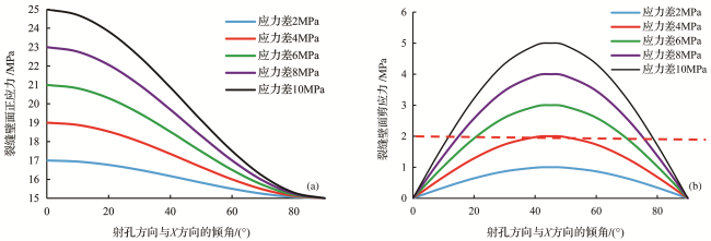
裂缝在转向扩展过程中,由于裂缝倾角的变化,造成裂缝壁面应力发生变化。为了研究它们之间的相互关系,设定最小主应力(沿x轴方向)为15MPa,应力差分别为2MPa、4MPa、6MPa、8MPa、10MPa,裂缝倾角为0°~90°。利用式(12)、式(13)可计算不同倾角下,裂缝壁面正应力、剪应力随主应力差的变化情况,计算结果如图1所示。
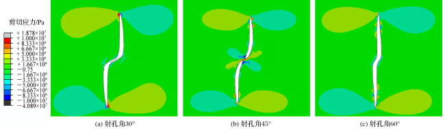
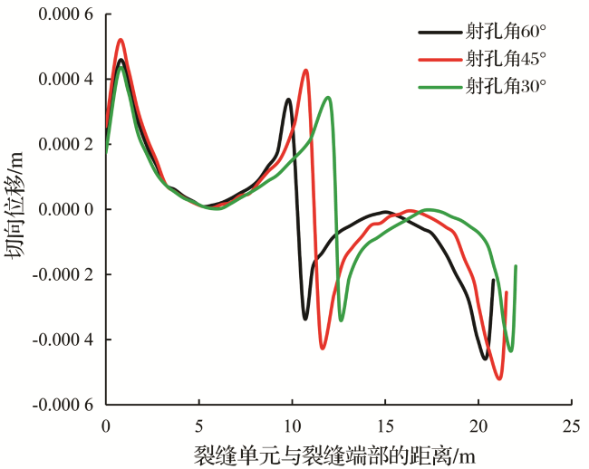
图1 不同裂缝倾角壁面应力随主应力差的变化关系

Fig. 1 Effect of principal stress difference on stress distribution of different fracture dip

图1表明,当主应力差相同时,裂缝壁面的正应力随着裂缝倾角的增加而减小,剪应力随着裂缝倾角先增大后减小,在裂缝倾角为45°时达到最大值;当裂缝倾角一定时,裂缝壁面正应力和剪应力随着主应力差的增加而增加。因此,高应力差会增加裂缝壁面的闭合压力,使裂缝张开困难,同时也会使裂缝壁面的剪应力增加,有利于产生剪切裂缝,剪切裂缝沿裂缝角度45°向两侧发育;从图1(b)可以看出,主应力差越大,剪切破坏区域越大。

2.2 射孔角度对裂缝剪应力的影响

Abaqus模拟输入的最小主应力为15MPa,主应力差为6MPa,杨氏模量为4 000MPa,泊松比为0.3,孔隙度为10%,流体黏度为0.001Pa·s,射孔角分别为30°、45°、60°,模拟采用流体为清水,裂缝沿射孔方向起裂。射孔角对裂缝壁面剪应力和剪切位移影响的模拟结果如图2图3所示。
图2 射孔角对裂缝剪切应力的影响

Fig. 2 Effect of perforating angle on shear stress

图3 裂缝各单元裂缝切向位移分布

Fig. 3 The distribution of shear displacement of each fracture element

图2表明,当射孔角为45°时,裂缝入口剪应力分布较大,在射孔角为30°、60°时,无此现象;随着射孔角度的增加,裂缝转向半径逐渐减小,这是因为随着角度增加,裂缝壁面正应力逐渐减小,裂缝更容易转向至最大主应力方向。图3表明,裂缝入口和端部产生的切向位移较大,在射孔角为45°方向达到最大值。因此在高应力差的条件下,沿45°方向射孔,更容易产生剪切裂缝。

3 裂缝间距对裂缝扩展的影响

在多簇射孔压裂过程中会产生多条裂缝同时延伸的情况,为了揭示多裂缝扩展延伸机理。在裂缝壁面应力分析的基础上,进一步研究了2条裂缝同时延伸,裂缝间距对裂缝几何形态、剪切应力、孔隙压力分布的影响。

3.1 裂缝间距对裂缝几何形态的影响

Abaqus模拟输入的最小主应力为15MPa,主应力差为6MPa,射孔角为45°,杨氏模量为4 000MPa,泊松比为0.3,孔隙度为10%,流体黏度为0.001Pa·s,裂缝间距(b)分别为8m、16m、30m。裂缝间距对裂缝几何形态及应力场影响的模拟结果如图4所示。
图4 裂缝间距(b)对裂缝几何形态的影响

Fig. 4 Effect of fracture spacing (b) on fracture geometry

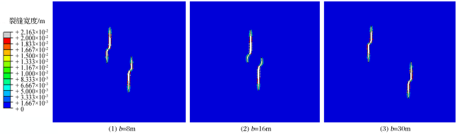
图4表明,随着裂缝间距的增加,裂缝之间的干扰逐渐减小;当裂缝间距为8m时,裂缝呈不对称延伸,裂缝相邻一侧发生严重干扰,产生相互吸引,裂缝延伸受阻且内侧裂缝缝宽窄。当裂缝间距增加至16m时,裂缝相互干扰减弱,裂缝内侧长度短于外侧;当裂缝间距为30m时,裂缝干扰进一步减弱,裂缝均呈对称分布。

3.2 裂缝间距对剪切应力的影响

Abaqus模拟输入的最小主应力为15MPa;主应力差为6MPa;射孔角为45°;杨氏模量为4 000MPa;泊松比为0.3;孔隙度为10%;流体黏度为0.001Pa·s;裂缝间距(b)分别为8m、16m、30m。裂缝间距对剪应力影响的模拟结果如图5所示。
图5 裂缝间距(b)对剪切应力的影响

Fig. 5 Effect of fracture spacing (b) on shear stress

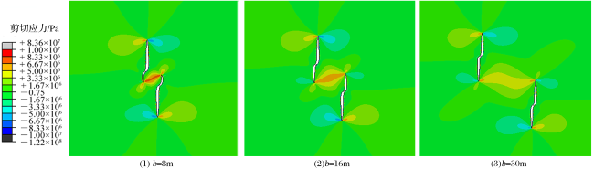
图5表明,随着裂缝间距的增加,内侧裂缝干扰区的剪应力逐渐减弱。当裂缝间距为8m时,虽然内侧裂缝延伸受阻,但干扰区的剪应力较大,岩石会产生更多的剪切破坏,以弥补内侧裂缝长度的不足。因此,缩短射孔族间距,可诱发剪切裂缝。
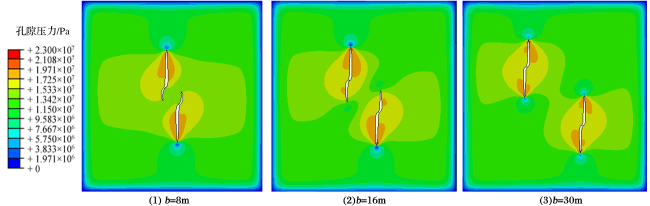
3.3 裂缝间距对孔隙压力的影响

Abaqus模拟输入的最小主应力为15MPa;主应力差为6MPa;射孔角为45°;杨氏模量为4 000MPa;泊松比为0.3;孔隙度为10%;流体黏度为0.001Pa·s;裂缝间距(b)分别为8m、16m、30m。裂缝间距孔隙压力的影响如图6所示。
图6 裂缝间距(b)对孔隙压力的影响

Fig.6 Effect of fracture spacing (b) on pore pressure

图6表明,随着裂缝间距的增加,裂缝两侧的孔隙压力分布逐渐趋于对称。当裂缝间距为8m时,由于内侧裂缝产生严重的应力干扰,导致内侧裂缝附近流体分布少,裂缝内压力低,造成裂缝无法延伸。因此,裂缝间的应力干扰会对裂缝内的流体分布产生影响,导致裂缝孔隙压力分布不均。

4 结论

(1)裂缝壁面的正应力随着裂缝倾角(裂缝与最小水平主应力方向夹角)的增加而减小,剪应力随着裂缝倾角先增大后减小且在45°方向达到最大值。在一定裂缝倾角下,高应力差会导致裂缝壁面正应力和剪应力同时增加。
(2)随着射孔角(射孔方向与最小主应力的夹角)的增加,裂缝转向半径减小。在高主应力差的条件下,射孔角为45°时,裂缝入口处剪应力较大,有利于岩石产生剪切破坏。
(3)多裂缝同时扩展过程中,随着裂缝间距的减小,内侧裂缝缝宽小,长度短,但是干扰区的剪切应力变大,有利于产生剪切破坏。
(4)随着裂缝间距的减小,裂缝应力干扰加强,导致内侧裂缝流体分布少,造成裂缝流体压力低,裂缝延伸受阻。
1
Zhao Jin , Zhang Sui’an , Ma Dongming , et al . Numerical simulator study for carbon dioxide injection ECBM recovery[J].Nature Gas and Oil, 2012, 6(1): 67-70.

赵金,张遂安,马东明,等 . 注二氧化碳提高煤层气采收率数值模拟[J]. 天然气与石油, 2012, 6(1): 67-70.

2
Zhao Jin , Zhang Sui'an , Cao Lihu . Comparison of experimental adsorption between shale gas and coalbed gas[J].Natural Gas Geoscience, 2013,24(1):176-181.

赵金,张遂安,曹立虎 . 页岩气与煤层气吸附特征对比实验研究[J]. 天然气地球科学, 2013,24(1):176-181.

3
Zhao Jin , Zhang Sui'an . Production dynamics of CBM bottom hole pressure[J]. Journal of Coal Goal & Exploration, 2013, 41(2): 40-45.

赵金, 张遂安 . 煤层气排采压降传播规律[J]. 煤炭科学技术, 2013, 41(2): 40-45.

4
Yuan Yu , Zhao Jin , Cao Lihu ,et al . Application of hydraulic sand jetting perforation to coalbed methane development[J]. Coal Science and Technology, 2016, 44(5): 68-73.

袁玉,赵金,曹立虎,等 . 水力喷砂射孔技术在煤层气开发中的应用 [J]. 煤炭科学技术,2016, 44(5): 68-73.

5
Wu Qi , Xu Yun , Zhang Shouliang , et al . The core theories and key optimization designs of volume stimulation technology for unconventional reservoirs[J]. Acta Petrolei Sinica, 2014, 35(4): 706-714.

吴奇,胥云,张守良,等 . 非常规储集层体积改造技术核心理论与优化设计关键[J]. 石油学报, 2014, 35(4): 706-714.

6
Zeng Qinglei , Zhuang Zhuo , Liu Zhanli , et al . Fully coupled modeling for multiple clusters growth of hydraulic fractures in shale[J]. Chinese Journal of Computational Mechanics, 2016, 33(4): 643-648.

曾庆磊,庄茁,柳占立,等 . 页岩水力压裂中多簇裂缝扩展的全耦合模拟[J]. 计算力学学报, 2016, 33(4): 643-648.

7
Xu Yun , Chen Ming , Wu Qi , et al . Stress interference calculation model and its application in volume stimulation of horizontal wells[J].Petroleum Exploration and Development, 2016, 43(5):780-786.

胥云,陈铭,吴奇,等 . 水平井体积改造应力干扰计算模型及其应用[J]. 石油勘探与开发, 2016, 43 (5):780-786.

8
Chen Mian . Re-orientation and propagation of hydraulic fractures in shale gas reservoir[J]. Journal of China University of Petroleum:Edition of Natural Science, 2013, 37(5):88-94.

陈勉 . 页岩气储层水力裂缝转向扩展机制[J].中国石油大学学报:自然科学版,2013, 37(5):88-94.

9
Weng Dingwei , Fu Haifeng , Bao Liqing , et al . Polyaxial test research on in-plane perforation for horizontal wells[J]. Natural Gas Geoscience, 2018, 29(4): 572-578.

翁定为,付海峰,包力庆,等 . 水平井平面射孔实验研究[J]. 天然气地球科学, 2018, 29(4): 572-578.

10
Zhao Jinzhou , Yin Qing , Li Yongming , et al . A pseudo-three-dimensional model for thermoelastic stress field around a re-fractured gas well[J]. Natural Gas Geoscience,2015,26(11): 2131-2136.

赵金洲,尹庆,李勇明,等 . 重复压裂气井热—固耦合应力场拟三维模型[J]. 天然气地球科学, 2015, 26(11): 2131-2136.

11
Pan Linhua , Zhang Shicheng , Cheng Lijun , et al . A numerical simulation of the inter-cluster interference in multi-cluster staffed fracking for horizontal wells[J]. Natural Gas Industry, 2014, 34(1):74-79.

潘林华,张士诚,程礼军,等 .水平井“多段分簇”压裂簇间干扰的数值模拟[J].天然气工业201434(1):74-79.

12
Zeng Fanhui , Guo Jianchun , Liu Heng , et al . Optimization design and application of horizontal well staged fracturing in tight gas reservoirs[J]. Acta Petrolei Sinica, 2013, 34(5):959-968.

曾凡辉, 郭建春, 刘恒, 等 . 致密砂岩气藏水平井分段压裂优化设计与应用[J]. 石油学报, 2013, 34(5): 959-968.

13
Deng Yan , Yin Jian , Guo Jianchun . A new calculation model for stress feld due to horizontal well staged fracturing[J]. Rock and Soil Mechanics, 2015, 36(3): 660-666.

邓燕,尹建,郭建春 .水平井多段压裂应力场计算新模型[J].岩土力学201536(3):660-666.

14
Zhao Jinzhou , Chen Xiyu , Liu Changyu , et al . The analysis of crack interaction in multistage horizontal fracturing[J]. Natural Gas Geoscience, 2015, 26(3): 533-538.

赵金洲,陈曦宇,刘长宇,等 .水平井分段多簇压裂缝间干扰影响分析[J].天然气地球科学, 201526(3): 533-538.

15
Li Yongming , Wang Yanchen , Zhao Jinzhou , et al . Calculation model of kink angle in shale gas reservoirs with consideration of stress interference[J]. Natural Gas Geoscience, 2015, 26(10): 1979-1983.

李勇明,王琰琛,赵金洲,等 .考虑多缝应力干扰的页岩储层压裂转向角计算模型[J].天然气地球科学, 2015, 26(10), 1979-1983.

16
Xu Jiaxiang , Ding Yunhong , Yang Lifeng , et al . Analysis of stress interference and geometry of hydraulic fractures based on the extended finite element method[J]. Natural Gas Geoscience, 2018, 29(9): 1356-1363.

徐加祥,丁云宏,杨立峰,等 . 基于扩展有限元的水力压裂缝间干扰及裂缝形态分析[J]. 天然气地球科学, 2018, 29(9): 1356-1363.

17
Belytschko T , Black T . Elastic crack growth in finite elements with minimal remeshing[J]. International Journal for Numerical Methods in Engineering, 1999, 45(5): 601-620.

18
Moës N , Dolbow J , Belytschko T . A finite element method for crack growth without remeshing[J]. International Journal for Numerical Methods in Engineering, 1999, 46(1): 131-150.

19
Dahi-Taleghani A , Olson J E , Numerical modeling of multistranded-hydraulic-fracture propagation : Accounting for the Interaction between induced and natural fractures[J]. SPE Journal,2011,16: 575-581.

20
Batchelor G K . An Introduction to Fluid Dynamics[M]. Cambridge: Cambridge University Press, 1967.

21
Atkinson B K . Fracture Mechanics of Rock[M]. New York:Geology Series, Academic Press, 1989.

22
Li Shiyu , He Taiming , Yin Xiangchu , et al . Introduction of Rock Fracture Mechanics[M]. Hefei: Press of University of Science and Technology of China, 2010: 45-46.

23
Erdogan F , Sih G C . On the crack extension in plates under loading and transverse shear[J]. Journal of Basic Engineering, 1963, 85 (4): 519-527.

24
Nuismer R . An energy release rate criterion for mixed mode fracture[J]. International Journal of Fracture,1975,11(2): 245-250.

Outlines

/